I have always been a man of science, and as such i would usually have a rough understanding of how everything works. However one thing that had always bugged me was computers. I could never work out how a computer could turn 1s and 0s flowing through logic gates into what you see before you.
So in the summer of 2010 when i was just finishing my GCSE's, I decided to do a little research in to the matter. So I did a few searches on YouTube, and came across this video, which shows you how to make a simple 4 bit adding circuit out of transistors. It contains a circuit diagram in logic gates of how to make a simple half adder. Intrigued, I went out to the shed to try build the thing.
Now I had never been very good with electronics; the only circuitry I ever really had done was with relays, so I thought I'd try and apply some of the principles shown in the video using relays. I started by making up a few basic logic gates and wiring them together into a simple half adder as shown at the beginning of the video. I then worked out how to do basic latch memory. Lo and behold, TIM 1 was born. You may be wondering why it was called TIM. Basically I just like the name Tim, but the official reason is because it stands for The Intelligent Machine... or something like that. When I powered it up it would add 2 binary digits together. This was surprisingly satisfying seeing as it wasn't very impressive, but it meant I had finally grasped the very basics of computing.

This first attempt, as shown above, was the start of a years worth of design and development and sweating over a soldering iron until the small hours of the morning, but I'll come to all that later.
In the days following, a rush of developments and breakthroughs occurred (some of which seem painfully obvious); I discovered that an XOR gate and an AND gate would do the same as the 3 AND's, 2 NOT's and an OR as used in TIM 1 (which meant spending ages trying to develop an XOR gate made from just 2 relays), That two wires soldered together would make an or gate instead of having to use 2 relays, and that a diode could be used instead of my special 'Isolators'. All these developments meant less relays were used for any particular system. This was critical as I only have the relay's I can find lying around, I wouldn't go out and buy them as that costs money which I don't have. Not that there wasn't enough of them; my dad's an electronic engineer and there's loads of junk lying around which I could tare up for parts, It's just finding them that was the problem. This lack of relays was to become the bane of the entire TIM project.
Anyway, back to the project. TIM 2 was much the same as TIM 1, It just had another bit of memory. TIM 3 on the other hand was a 3 bit full adder, with control panel. This was where things began to get interesting:

I always remember the first time I switched it on. Not a particularly interesting event in theory, but just seeing that power light turn on and the power supply fan starting up gave the same sort of excitement I get when one of my vehicles moves under it's own power for the first time. It felt like a real computer, even if it was only capable of the most basic additions.
TIM 4 was much the same as TIM 3, just now it was a 4 bit full adder.
TIM 5 was my first attempt at a real computer (of sorts). I basically took TIM 4 and added 3 registers (memory blocks) ,a clock and a whole bunch of control circuitry. It looked awesome (in a kind of Heath Robinson-y way ) as I practically soldered up the relays where they happened to be at the time, meaning there was wires everywhere, Look at the picture below and you'll see what I mean:

It could now do multiplication and incrementation as well as addition up to 31, however it was impossible to move anywhere as you had to move each relay individually. Here's a video of it incrementing up to 16. I eventually took it apart to make TIM 6, A more compact and simplified version of TIM 5 as shown below:


I've added the photo of the underside to just to give you an idea of the problems faced when trying to find bugs in the system. I never made any circuit diagrams for it since I made it up as i was going along, so I had to remember where all the wires went. There was one fault which caused it to go haywire occasionally which I never found until I finally disassembled it (one of the capacitors in the C register had become unsoldered for anyone who's interested).
Things started to get serious from now on. By this time I wanted a real working CPU capable of running programs rather than just the simple calculators I'd been constructing. I started the design of TIM 7 at the end of the summer holiday's, and only finished the plans for it around Christmas.

It was originally going to be a very simple 4 bit adder, basically TIM 6 with punch tape instead of a control panel. Then i upgraded the design to a full 5 bit punch tape computer with all the standard ALU commands, as shown above. However I still didn't like the design all that much so completely redesigned it as a serial ALU, 8 bit punch tape computer which was much neater. Although TIM 7 was never built, i called the last one TIM 8, partly because TIM 7 had so many plans for it, and partly because it better suited an 8 bit computer.
TIM 8 by contrast only took a few weeks to design, this was mainly because I'd worked out all the hard while stuff designing TIM 7. The problem was I'd now found all the relays there were to be found, and that only came up to about 150. I've never seen an 8 bit relay computer built in less than 281 relays, and most of those were 4 pole relay, where as mine are nearly all single pole. So I had to take the simplification to extreme lengths. The advantage of running it straight off the tape reader is that you didn't require a program counter, or a finite state machine, or a clock, which saves a good hundred relays at least. Then there is the serial ALU, which although slower than a parallel one, allows greater flexibility and uses far less relays.
Another problem that had occurred was that I refuse to use a RAM chip for memory, because it's a RELAY computer, not a relay-with-several-million-transistors-thrown-in-because-I'm-to-lazy-to-do-it-properly computer. As such I'm only allowing technology which was around before the time of ENIAC. Almost every other relay computer I've seen uses a RAM chip, which is only vaguely acceptable as they're using the Von Neumann Architecture (Computer data and program are stored in the same memory) , where as I'm using the Harvard Architecture (Computer data and program are stored in separate memories, in my case the program is stored on the punch tape). This means the amount of memory I have doesn't limit the length of program I can write, however it still limits the amount of data the computer can process. So I designed in five 8 bit registers. But that uses a huge amount of relays and only stores 5 bytes, which isn't really enough for anything exciting. I had also just redesigned my memory addressing system so that it allowed 16 bytes of memory to be stored. The problem was now that i had very few relays left, so making all of that out of relay latch memory wasn't possible. I therefore set about researching all the different kinds of computer RAM that had ever been developed to try find one which I could use, however they all were horribly complex and required large amounts of decoding hardware. Therefore I had to design my own. I decided to use capacitors as they were the only component I had which could store data easily. So I spent the next week or so trying loads of different designs out, looking at the problems encountered and redesigning accordingly. eventually I came up with the following design, which only uses one relay pole per byte:

This meant I could now use all of my addressable memory with out having to resort to modern IC's. It does mean I'm going to have to buy around 100 capacitors and 200 diodes, but they are much cheaper than relays, and it should look cool when done (I haven't built a full scale version yet, only a 2x2 bit prototype)
Here is the finished design of TIM 8. As of this post, I have built pretty much everything except the capacitor memory so far.

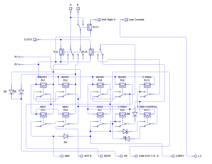
Below is a picture of the ALU panel with it's supporting hardware to give you an idea of what it looks like. The photo is somewhat out of date as various things have changed, but for the most part it's the same. The ALU in the centre does all 8 logic processes for the computer, so is basically TIM's brain. It took a long time and a lot of effort to get it down to just 12 relays (The one on TIM 7 would have used 40), However it does require the parallel to serial converters and command selector etc. which brings the relay count up slightly, but it's still pretty decent. The 1 bit nature of the ALU does allow useful tricks such as variable bit width, so you can string 2 or more registers together if you need to process numbers greater than 8 bit. Alternatively, you could use half a register for one 4 bit number, and the other half for another to increase memory capacity.

This is a picture of the actual circuit diagram for the ALU, showing all 8 function outputs. It was drawn up in Circuit Wizard, which was where the design for this ALU was finalized:
Below is (quite a poor) photo of an almost completed T.I.M. on my desk. I had to build it on the sheets which eventually became the case, or it would have been very hard to make it fit:

This is one of an almost completed T.I.M. in his box. From the photo above to the photo below was about one school week. This rapid development was due to the fact I had heard there was to be a science fair that Friday, and decided it would be a good deadline in which to finish TIM, or it would never get done. Some very late nights later and TIM was pretty much done. I took it into school the next day almost entirely untested, and after an hour trying to fix a fault (turned out the tape reader head had moved slightly), it ran an increment program for 2 hours continuously without fault (We eventually turned it off, the clicking was driving us insane). Admittedly the increment command was all he could do at that point, seeing as i had wired up the A and B inputs to the ALU the wrong way round, but i only discovered that the next day. To see a video of it running, click here.

The BIOS of T.I.M. is called B.L.T. (Basic Language of Tim/ My favourite sandwich). It is designed in the way to use the smallest possible amount of relays for decoding, and yet keep it Turing complete. It is a little bit of a Turing Tarpit language, but it's still surprisingly flexible. As the ALU is serial, each bit has to be addressed to pass through it. This means you have 8 commands for any ALU instruction. This may seem excessive, but it means that, for example, if i wanted to store two 4 bit numbers separately, i could store them in the same register or alternatively, as the carry has it's own register and is fed back in to each computation, I can link registers together to hold larger numbers. So when T.I.M.'s memory is finished, it should be able to hold numbers equivalent to around 3.4x10^38... which is pretty big (128 bits). However, for addressing commands you only need a 3 bit address, and the address in is 4 bits across. Therefore I've used this to allow me to address to working registers (B and C) which means I can work on more numbers where they are instead of having to move them into a different memory location (which there are very few of). This means that if I was counting using a flag (for example) then I could increment my flag in one register, and do all the workings in the other.
I have also left out commands I can do in other ways using more commands. E.G. there is no INC command as this would take an extra command and be hard to do on a serial ALU. However to increment you 'set carry to 1', 'Disable input A' and then ADD A and B to increment B. Again this means the computer is more flexible as you can increment single digits or huge numbers with much less relays. Despite being so simple I'm always having to update the language where I've hardwired it into T.I.M. wrong or written it down wrong. For example none of my more complex programs worked previously, and this was because I'd written down 'Disable input A' as 'Disable input B/C' which meant I was always trying to increment A which won't work.
Another thing I did to save relays was doing away with the clock and finite state machine that times all the commands in the computer. If you look at the tape, the commands are much longer than the execute line to let the relays settle in the right position before a command is processed. To do any other timings I have used capacitors. This reduces the speed I can run the computer, but speed wasn't what T.I.M. was designed for.
Here is a picture explaining the language (commands in brackets have not yet been added):

Programs are written as bytes in note pad, then compiled into a .bmp file using a little program I wrote. These are then printed out on to tape using a recipt printer. This method is substantially easier than the original punched tape programs that you got on old computers, as I would have had to punch each program out by hand, and most mistakes would require a complete re-punch of the program.
I have written a program that almost amounts to an operating system now; basically what it is is a basic calculator program, where you input a number, give it an operation such as + ,- ,X ,or /, then input another number. The program then runs, then places the result in the first input register, loops back, and allow's you to give another function and another number. It's sort of working, but since the tape is around 4 meters long it took an age to print (only allows me to print in 30cm sections for some reason) I haven't printed out the debuged vertion, as i want to find as many bugs as possible first.
Below is a little program that just increments the B register. This is the form in which it would be printed out, with annotations added. This program can be seen running in this video.

This page is no longer updated, but if you want more recent information on TIM please visit the official website at http://www.northdownfarm.co.uk/rory/tim/
(The information is mostly the same, but it includes recent updates which this page does not.)
hi, i been working on parts for a relay computer, i was wondering if share them with u and get your input?
ReplyDelete